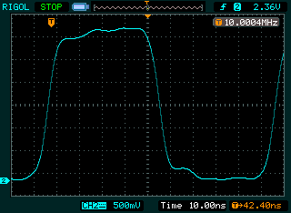

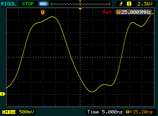
As expected, the result looks quite decent. Next, I used a 5kOhm resistive probe:
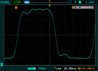
There is a bit more bounce on the signal, but it's still fairly calm. Now I switched to the scope's standard capacitative 1:10 probe:
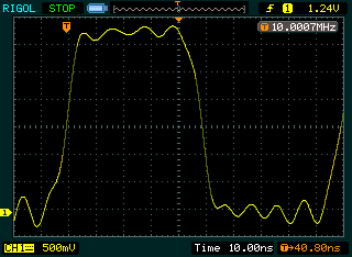
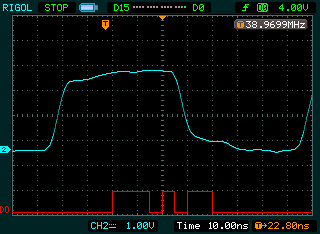
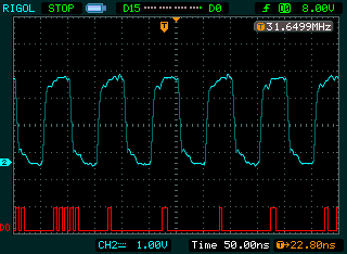
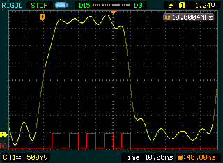
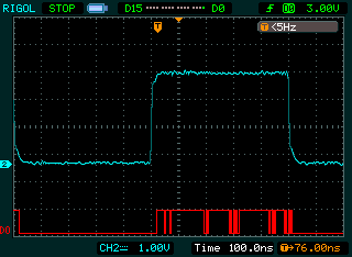
Quite clearly, those electrons are beginning to have a party. Finally I've attached the LA probe, digital threshold set to 8V:
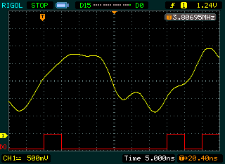
Not pretty.
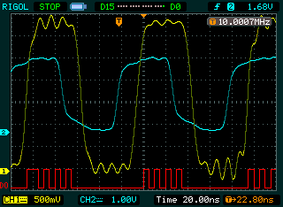
The yellow curve is the input to the LA, the blue curve is the sync output of the function generator, and the red curve is what the LA imagines is happening at the 8V threshold.
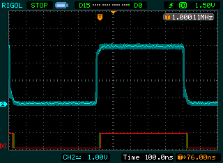
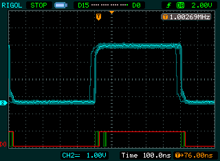
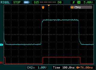
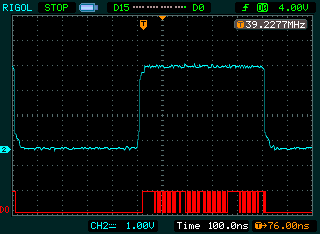
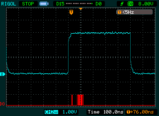
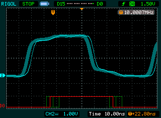
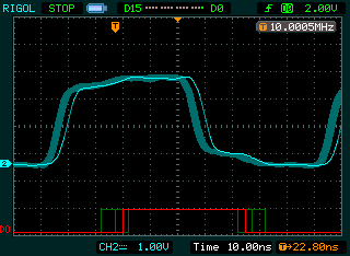
The 1.5V and 2V results were good enough that I enabled persistence to show how many glitches I got. There was a small number at 2V while 1.5V is clean. 3V varied between great and awful.
The scope shows "<5Hz" for the trigger frequency in the 3V cases and the 8V case because I had set it to single sweep. In all other cases, it was set to normal sweep.
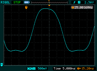
And here's the same show for 10MHz, 1.5V, 2V, 3V, 4V, and 8V: